
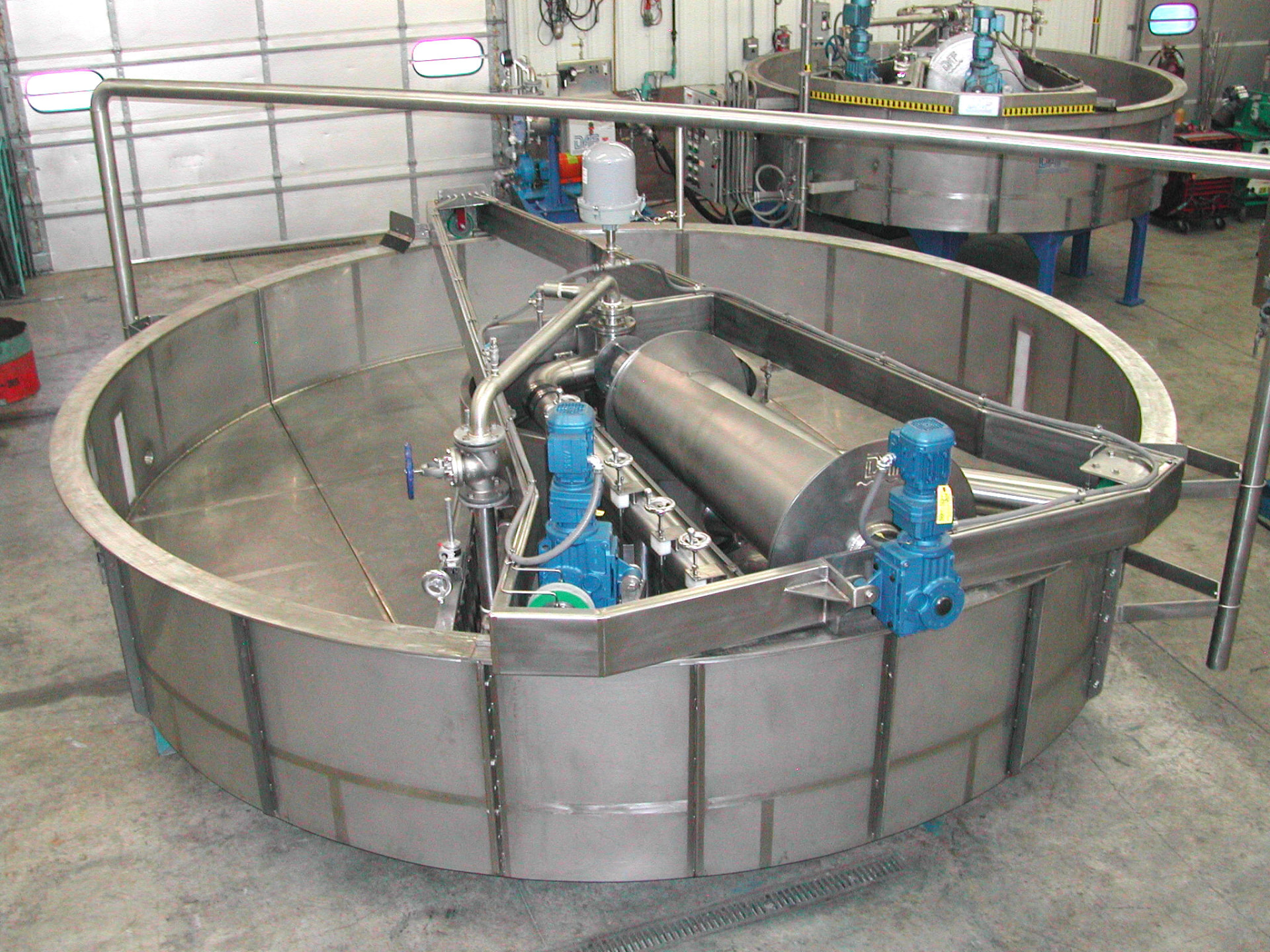
FC Maximizer Model Dimensions and Capacity
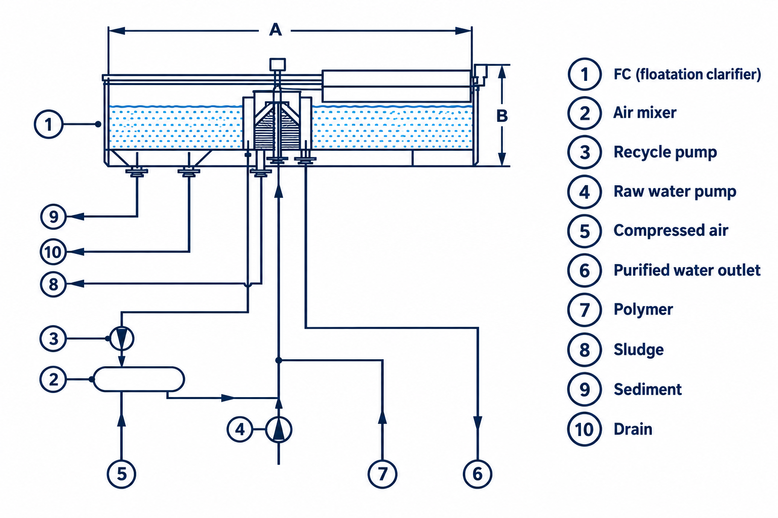
Use this table to compare preliminary installation dimensions and flow ratings across the FC Maximizer line. Diameter A and height B correspond to the labeled dimensions in the side-view diagram below.
The two flow columns describe different operating references. Total hydraulic flow is the clarifier's full hydraulic capacity. Flow including 25% recycle is the real-world process flow after reserving capacity for the recycle stream. For example, the FC 700 is rated at 11,950 GPM total hydraulic capacity and 8,850 GPM with 25% recycle.
| Model | Diameter A ft | Height B in | Total Hydraulic Capacity GPM | Flow with 25% Recycle GPM |
|---|---|---|---|---|
| FC 40 | 4 | 45 | 29 | 22 |
| FC 60 | 6 | 45 | 60 | 48 |
| FC 80 | 8 | 45 | 130 | 110 |
| FC 100 | 10 | 50 | 245 | 200 |
| FC 120 | 12 | 52 | 350 | 300 |
| FC 150 | 15 | 60 | 550 | 400 |
| FC 180 | 18 | 62 | 790 | 600 |
| FC 200 | 20 | 64 | 975 | 700 |
| FC 220 | 22 | 66 | 1,180 | 850 |
| FC 240 | 24 | 66 | 1,400 | 1,000 |
| FC 270 | 27 | 68 | 1,785 | 1,200 |
| FC 300 | 30 | 72 | 2,200 | 1,500 |
| FC 330 | 33 | 74 | 2,660 | 1,900 |
| FC 360 | 36 | 76 | 3,170 | 2,300 |
| FC 400 | 40 | 78 | 3,900 | 2,800 |
| FC 440 | 44 | 80 | 4,750 | 3,400 |
| FC 490 | 49 | 84 | 5,460 | 4,200 |
| FC 550 | 55 | 86 | 7,400 | 5,500 |
| FC 620 | 62 | 95 | 9,400 | 6,900 |
| FC 700 | 70 | 98 | 11,950 | 8,850 |
Preliminary selection only. Final model sizing depends on wastewater characteristics, peak flow, solids loading, treatment chemistry, recycle ratio, effluent targets, and site conditions.
How to Use This Table
The FC Maximizer line runs from the FC 40, a 4 ft diameter unit rated at 29 GPM total hydraulic capacity, to the FC 700, a 70 ft diameter unit rated at 11,950 GPM. Work through these steps for a preliminary match.
- Start with your peak flow, not your average flow.
- Decide which flow basis you are using. If your design flow is the process flow after the recycle stream is reserved, compare it with the "Flow with 25% Recycle" column. For example, the FC 200 is rated at 975 GPM total and 700 GPM with 25% recycle.
- Check diameter A and height B against the space available at your site.
- Send us your flow and wastewater details. An engineer will confirm the model, recycle requirement, and chemistry.
Not sure whether a round unit is right for your plant? Read our comparison of round and rectangular DAF clarifiers. For the process behind the equipment, see how dissolved air flotation works.
How the FC Maximizer Is Arranged
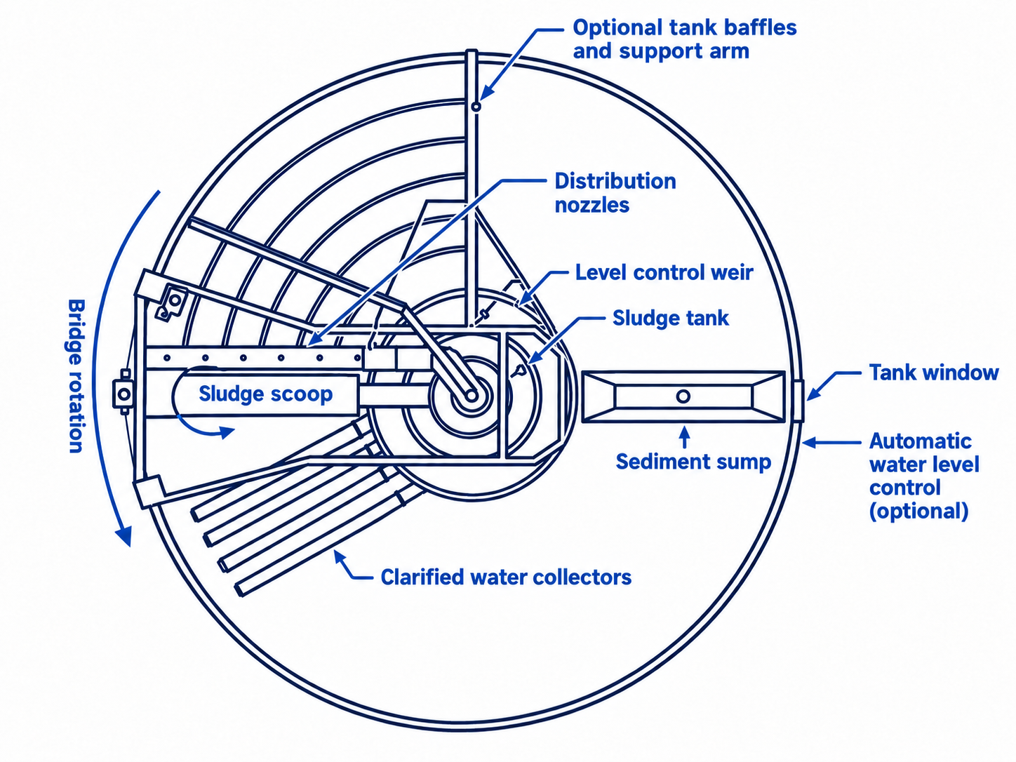
These reference diagrams identify the primary collection, skimming, level-control, recycle, and discharge components used in a typical FC installation. Project drawings are engineered for the selected model and site.
Confirm the Right FC Model for Your Plant
Share your peak flow, wastewater characteristics, and discharge targets. A DAF Corporation engineer will confirm the model, recycle requirement, chemistry, and site-specific configuration.